
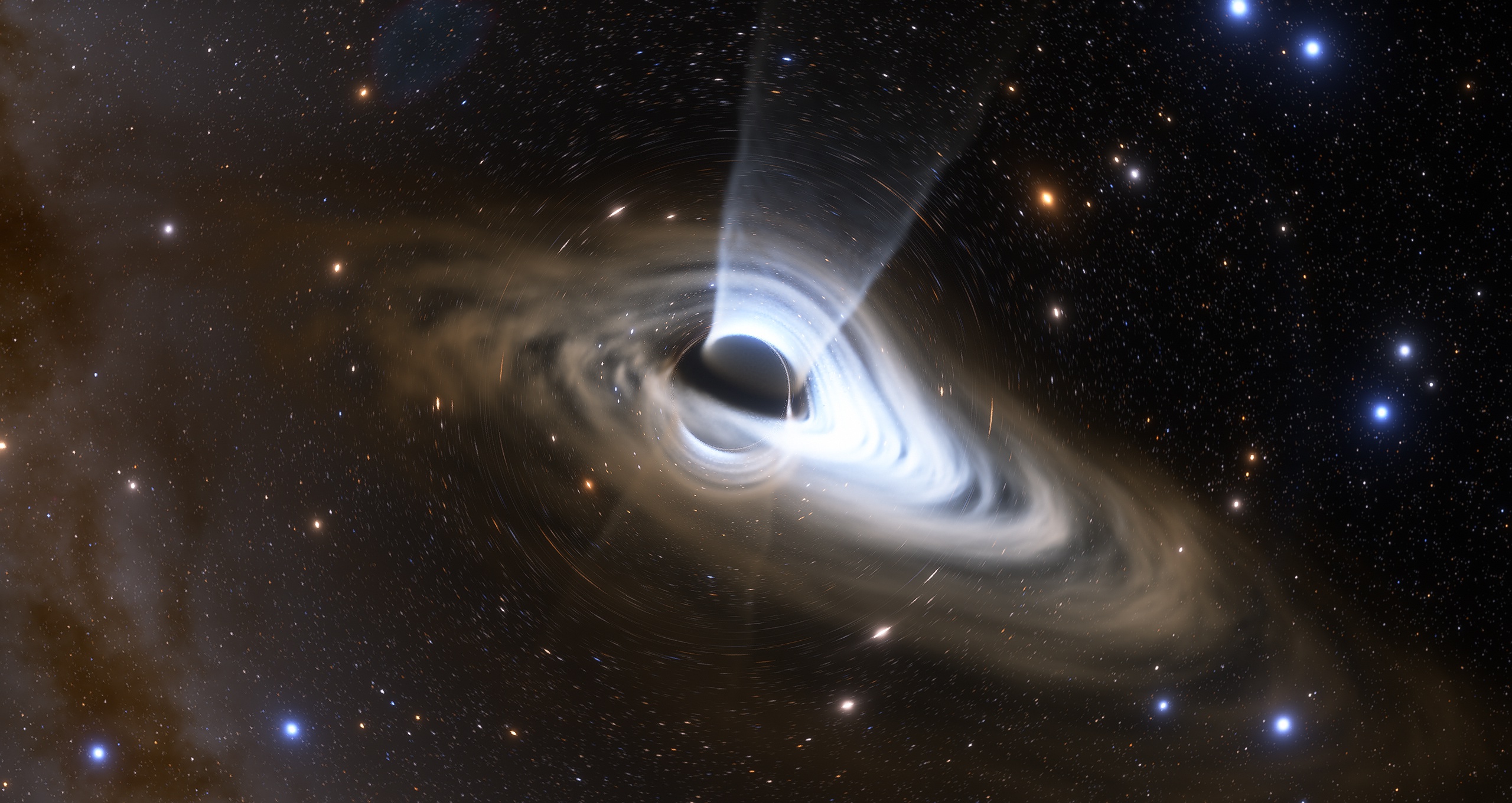
Visualizing General Relativity
When thinking about renders of things like warp drives and black holes we usually just expect to see a simple approximation or an artist rendition, assuming the math required to pull off something accurate would require someone with at least a PhD in Mathematical Physics. Which I won’t tell that its completely untrue, but in this blog post I’ll try to explain a way to do quite accurate visualizations within a 100 or so lines of code, for basically any kind of space-time for which you can write its metric as code. Although, the detailed mathematical derivation of this approach might be somewhat math heavy.
The main ingredient of any GR render is figuring out how the rays of light move around. Knowing how light moves we can trace rays from the camera into the scene and see where the light came from. So, to render the simplest scene without objects we simply trace a ray for each pixel and assign the color of the pixel to the color of the skybox in the direction in which the ray ends up pointing to.
- What are geodesics?
- Mathematical description of shortest path
- Lagrangian description of a geodesic
- Hamiltonian description of a geodesic
- Writing a Hamiltonian geodesic tracer in GLSL
- Conclusions
- References
What are geodesics?
How exactly do we trace rays in curves space? Any object inside a curved space follows something called a geodesic.
A geodesic is just a fancy word for, in some sense, a path of shortest length between 2 points inside a space.
I should note that there could be multiple of such paths, which are locally minimal, in the sense that you can’t nudge the path to make it shorter, while globally there might be a shorter path. Also, in Minkowski space-time the definition is a bit more complicated, because of the imaginary distances (when \( ds^2 < 0 \) ).
In our case, instead of paths between 2 points, we are only interested in finding how a ray moves given an initial point and direction, but the definition above will still prove useful when deriving the equations describing a geodesic, which we will use here.
Mathematical description of shortest path
I’ll try to quickly go through the derivation. If you wish to skip the math part, jump to Writing a Hamiltonian geodesic tracer in GLSL.
Mathematically speaking we have some coordinate system, a path, and a way to compute distances between 2 points.
A coordinate system being a set of several numbers labeling each point in the space. A path is a function that takes in the path parameter and outputs a coordinate, in General Relativity the path parameter is usually proper time (like a clock moving with the object, labeling each point), but it can be anything really. The way to compute distances is called a metric (and it’s the main source of scary math here).
In physics, or more generally differential geometry, a metric is defined as an integral(“sum”) of something called the metric tensor. A metric tensor is a bilinear form \( g(a, b) \), it essentially maps pairs of vectors to real numbers, and is a generalization of dot product for curved spaces. So using a metric tensor we can find the length of a vector in space, and also distances \( ds \) between infinitely close points in space.
\begin{equation} ds^2 = g(dx, dx) \end{equation}
In our case, where we describe vectors as a set of numbers, a metric is simply a matrix product of some matrix \( g_{\mu \nu} \) times the vectors. For our infinitesimal distance \( ds \) we get this expression:
\begin{equation} ds^2 = \sum_{\mu \nu}^N g_{\mu \nu} dx^\mu dx^\nu \end{equation}
Usually the sum is just implicitly assumed by Einstein notation [1].
\begin{equation} ds^2 = g_{\mu \nu} dx^\mu dx^\nu \end{equation}
Here we can actually see that for some simple choice of \( g_{\mu \nu} \) we can get the distances by Pythagoras’ theorem. Specifically for the case when the metric tensor matrix is a unit matrix.
\begin{equation} ds^2 = dx_1^2 + dx_2^2 + dx_3^2 \end{equation}
For a flat space-time like space, we get something similar but with the exception that the time coordinate component is with a negative sign.
\begin{equation} ds^2 = - dx_0^2 + dx_1^2 + dx_2^2 + dx_3^2 \label{flat} \end{equation}
Here I used the \( (- + + +) \) signature, but signs can actually be flipped without changing the geodesics, and in some cases, like for particle physics, it makes more sense to use the opposite \( (+ - - -) \) signature.
Going back to the main question of computing distances, to compute the length between 2 points, A and B, along some path \( x^i(t) \) we simply need to sum the infinitesimal distances together using an integral:
\begin{equation} l = \int_A^B \sqrt{g_{\mu \nu} dx^\mu dx^\nu} = \int_A^B \sqrt{g_{\mu \nu} dx^\mu dx^\nu} \frac{dt}{dt} = \int_A^B \sqrt{g_{\mu \nu} \frac{dx^\mu}{dt} \frac{dx^\nu}{dt}} dt \end{equation}
Where \( \frac{dx^i}{dt} \) is simply how fast the coordinate x changes with respect to the path parameter (“clock”), in some sense can be interpreted as the velocity.
Now our main question is how do we minimize the path length? Here is where we introduce a thing called calculus of variations, which is roughly speaking a way to find how a functional(distance) changes by infinitesimally small variations of its input function(path). Such derivatives have similar properties to normal function derivatives. And in fact, similarly to calculus, to find the extremum of a function (min, max or stationary point), we simply need to equate the variation to 0.
Lagrangian description of a geodesic
There is an entire branch of physics related to variational principles, which states that any kind of physical system has a value it likes to minimize (or more generally make unchanging under small variations of path, i.e. “stationary”). That value is called action, and the function under the integral is called the Lagrangian function of the system. The branch of physics studying Lagrangian functions of systems is called Lagrangian mechanics.
In our case the Lagrangian can be written like this:
\begin{equation} L = \sqrt{g_{\mu \nu} \frac{dx^\mu}{dt} \frac{dx^\nu}{dt}} \end{equation}
Turns out we don’t need the square root for the minimum of the functional to be a geodesic, and we can simply remove it from our geodesic Lagrangian:
\begin{equation} L = g_{\mu \nu} \frac{dx^\mu}{dt} \frac{dx^\nu}{dt} \end{equation}
The proof of this you can find here [2]. The only difference such simplification makes is that the parametrization of the path might be different, but the path itself will be the same. Also notably, the equations for this specific case turn out to be the same, meaning the parametrization is also the same.
Additionally, we want this with a 1/2 factor, to simplify the equations down the line.
\begin{equation} L = \frac{1}{2} g_{\mu \nu} \frac{dx^\mu}{dt} \frac{dx^\nu}{dt} \end{equation}
So, our goal right now is to minimize this functional:
\begin{equation} S = \int_A^B \frac{1}{2} g_{\mu \nu} \frac{dx^\mu}{dt} \frac{dx^\nu}{dt} dt \end{equation}
In general the minimum of a functional like this can be found by applying the Euler-Lagrange equations [3]:
\begin{equation} \frac{\partial L}{\partial x^i} - \frac{d}{dt} \frac{\partial L}{\partial \frac{dx^i}{dt}} = 0 \label{el} \end{equation}
Euler-Lagrange equation derivation
In general, the Action can be written like \begin{equation*} S = \int_A^B L(t, x(t), \frac{dx(t)}{dt}) dt \end{equation*} Where the Lagrangian is a function of the path parameter, the path itself, and the derivative of the path with respect to the path parameter(also known as the generalized velocity). To find the minimizing path (or more generally, stationary path) of a functional we need to equate the variation of the action to 0 \begin{equation*} \delta S = 0 \end{equation*} Where the variation of the action is found by adding a small variation \( \delta x \) to the path: \( L(t, x + \delta x, \frac{d(x + \delta x)}{dt}) \) and expanding the 2D Taylor series around the point \( \left( x, \frac{dx(t)}{dt} \right)\) \begin{equation*} \delta S = \int_A^B \left( \frac{\partial L}{\partial x} \delta x + \frac{\partial L}{\partial \frac{dx}{dt}} \frac{d(\delta x)}{dt} \right) dt \end{equation*} We dropped the higher order terms since we assume \( \delta x \) to be infinitesimally small. Then we use integration by parts to get the derivative \( \frac{d}{dt} \) off the path variation \begin{equation*} \delta S = \int_A^B \left( \frac{\partial L}{\partial x} \delta x - \frac{d}{dt} \frac{\partial L}{\partial \frac{dx}{dt}} \delta x \right) dt + \left( \frac{\partial L}{\partial \frac{dx}{dt}} \delta x \right) \biggr \rvert_A^B \end{equation*} Since we keep the endpoints of the path stationary the last term is equal to zero: \begin{equation*} \delta S = \int_A^B \left( \frac{\partial L}{\partial x} \delta x - \frac{d}{dt} \frac{\partial L}{\partial \frac{dx}{dt}} \delta x \right) dt = \int_A^B \left( \frac{\partial L}{\partial x} - \frac{d}{dt} \frac{\partial L}{\partial \frac{dx}{dt}} \right) \delta x dt \end{equation*} Equating this to zero we get \begin{equation*} \int_A^B \left( \frac{\partial L}{\partial x} - \frac{d}{dt} \frac{\partial L}{\partial \frac{dx}{dt}} \right) \delta x dt = 0 \end{equation*} Which holds true when the path satisfies the expression under the integral \begin{equation*} \frac{\partial L}{\partial x} - \frac{d}{dt} \frac{\partial L}{\partial \frac{dx}{dt}} = 0 \end{equation*} Which is the Euler-Lagrange equation!You can find a more detailed derivation here [4]
Let’s derive the Euler-Lagrange equations for our geodesic Lagrangian (keep in mind that there is an equation for each coordinate \( x^i \) ):
\begin{equation} \frac{\partial L}{\partial \frac{dx^i}{dt}} = \frac{1}{2} \frac{\partial }{\partial \frac{dx^i}{dt}} g_{\mu \nu} \frac{dx^\mu}{dt} \frac{dx^\nu}{dt} = \frac{1}{2} g_{i \nu} \frac{dx^\nu}{dt} + \frac{1}{2} g_{\mu i} \frac{dx^\mu}{dt} = g_{i \nu} \frac{dx^\nu}{dt} \label{el0} \end{equation}
Then we take the derivative with respect to the path parameter:
\begin{equation} \frac{d}{dt} \left( g_{i \nu} \frac{dx^\nu}{dt} \right) = \frac{d g_{i \nu} }{dt} \frac{dx^\nu}{dt} + g_{i \nu} \frac{d^2x^\nu}{dt^2} = \frac{d g_{i \nu} }{dx^\mu} \frac{dx^\mu}{dt} \frac{dx^\nu}{dt} + g_{i \nu} \frac{d^2x^\nu}{dt^2} \label{el1} \end{equation}
And lastly:
\begin{equation} \frac{\partial L}{\partial x^i} = \frac{1}{2} \frac{d g_{\mu \nu} }{dx^i} \frac{dx^\mu}{dt} \frac{dx^\nu}{dt} \label{el2} \end{equation}
Substituting \eqref{el1} and \eqref{el2} into Euler-Lagrange equations \eqref{el} leads us to the equation of a geodesic:
\begin{equation} \frac{1}{2} \frac{d g_{\mu \nu} }{dx^i} \frac{dx^\mu}{dt} \frac{dx^\nu}{dt} - \frac{d g_{i \nu} }{dx^\mu} \frac{dx^\mu}{dt} \frac{dx^\nu}{dt} - g_{i \nu} \frac{d^2x^\nu}{dt^2} = 0 \end{equation}
Multiplying by the metric tensor inverse \( - g^{i \nu} \) we get:
\begin{equation} \frac{d^2x^i}{dt^2} + g^{i \nu} \left( \frac{d g_{i \nu} }{dx^\mu} - \frac{1}{2} \frac{d g_{\mu \nu} }{dx^i} \right) \frac{dx^\mu}{dt} \frac{dx^\nu}{dt} = 0 \end{equation}
And that’s our final system of equations for a geodesic, we could of course also substitute the Christoffel symbols here, but for our application there is no difference. Of course, we could just use these equations for tracing geodesic rays and call it a day, but unfortunately this would require computing a whole lot of derivatives (in 4d space-time it’s 64 of them to be specific), either manually, or by using numerical differentiation. Thankfully there is a way to avoid this, and in fact simplify the entire algorithm! (At a slight performance cost)
Hamiltonian description of a geodesic
So here comes the star of the show - Hamiltonian mechanics. Hamiltonian equations of motion have a really nice form which allows to easily write a computer program that integrates them by using Euler integration.
\begin{equation} \frac{dp^i}{dt} = - \frac{\partial H}{\partial x^i} \end{equation} \begin{equation} \frac{dx^i}{dt} = \frac{\partial H}{\partial p^i} \end{equation}
Where \( p \) is the so called generalized momentum, it’s the derivative of the Lagrangian with respect to the coordinate path parameter derivative.
\begin{equation} p_i = \frac{\partial L}{\partial \frac{dx^i}{dt} } \label{momentumdef} \end{equation}
And to get the Hamiltonian itself you need to apply the Legendre Transform [6] on the Lagrangian:
\begin{equation} H = \sum_{i}^N p^i \frac{dx^i}{dt} - L \label{legandre} \end{equation}
Hamilton equations of motion derivation
Lets start by writing down the Euler-Lagrange equation \begin{equation*} \frac{\partial L}{\partial x} - \frac{d}{dt} \frac{\partial L}{\partial \frac{dx}{dt}} = 0 \end{equation*} You can see that \( \frac{\partial L}{\partial \frac{dx}{dt} } \) is equal to our definition of generalized momentum \eqref{momentumdef}, so we can substitude it here \begin{equation*} \frac{\partial L}{\partial x} - \frac{dp}{dt} = 0 \end{equation*} Now lets substitude \(H\) instead of \(L\) by using the definition \eqref{legandre} \begin{equation*} \frac{\partial}{\partial x} \left( p \frac{dx}{dt} - H \right) - \frac{dp}{dt} = 0 \end{equation*} The partial derivative of \( p \frac{dx}{dt} \) with respect to \(x\) is 0, since changing \(x\) doesn't change \( p \) or \( \frac{dx}{dt} \) \begin{equation*} \frac{\partial}{\partial x} \left(- H \right) - \frac{dp}{dt} = 0 \end{equation*} After moving things around \begin{equation*} \frac{dp}{dt} = - \frac{\partial H}{\partial x} \end{equation*} Which is our first equation. Now lets take the partial derivative of \eqref{legandre} with respect to generalized momentum \begin{equation*} \frac{\partial H}{\partial p} = \frac{\partial}{\partial p} \left( p \frac{dx}{dt} \right) - \frac{\partial L}{\partial p} \end{equation*} Since \(L\) doesn't depend on \(p\) (as the value of \(L\) doesn't depend on its partial derivative), it means that \( \frac{\partial L}{\partial p} = 0 \), so we get \begin{equation*} \frac{\partial H}{\partial p} = \frac{\partial}{\partial p} \left( p \frac{dx}{dt} \right) \end{equation*} \begin{equation*} \frac{\partial H}{\partial p} = \frac{dx}{dt} \end{equation*} \begin{equation*} \frac{dx}{dt} = \frac{\partial H}{\partial p} \end{equation*} Which is our second equation.A different derivation of Hamilton’s equations of motion can be found here [5].
And for our case the momentum would be the following, which we already computed when writing down the Euler-Lagrange equations \eqref{el0}, and given the definition of generalized momentum \eqref{momentumdef}:
\begin{equation} p_i = g_{i j} \frac{dx^j}{dt} \label{momentum} \end{equation}
To get the “time” derivatives you simply need to multiply both sides by the metric tensor inverse:
\begin{equation} \frac{dx^i}{dt} = g^{i j} p_j \label{dxdt} \end{equation}
And the Hamiltonian itself:
\begin{equation} H = \sum_{i}^N \frac{dx^i}{dt} p_i - L = g_{i j} \frac{dx^i}{dt} \frac{dx^j}{dt} - \frac{1}{2} g_{i j} \frac{dx^i}{dt} \frac{dx^j}{dt} = \frac{1}{2} g_{i j} \frac{dx^i}{dt} \frac{dx^j}{dt} = L \end{equation}
Turns out that for this simple choice of a geodesic Lagrangian, the Hamiltonian is equal to the Lagrangian!
Also, we want to know the Hamiltonian as a function of the generalized momentum by substituting \eqref{dxdt} into the Hamiltonian equation:
\begin{equation} H = \frac{1}{2} g_{i j} \frac{dx^i}{dt} \frac{dx^j}{dt} = \frac{1}{2} g^{i j} p_i p_j \label{hamiltonian} \end{equation}
While the equations of motion will simply be:
\begin{equation} \frac{dp_i}{dt} = - \frac{\partial H}{\partial x^i} \label{eqmotion1} \end{equation}
\begin{equation} \frac{dx^i}{dt} = g^{i j} p_j \label{eqmotion2} \end{equation}
This is all we need to write a numerical geodesic integrator!
Writing a Hamiltonian geodesic tracer in GLSL
You might have noticed that in the final Hamilton’s equations of motion I didn’t write out \( \frac{\partial H}{\partial x^i} \), this is actually important! We want to keep the derivative of the Hamiltonian as is, because then instead of computing the 64 derivatives of the metric tensor, we only need 4 to find the Hamiltonian gradient. This is the main simplification of the geodesic tracing algorithm.
Here we will use the GLSL shading language, since it has variables and functions which map quite well to the mathematical operations we will perform here. On top of that we can easily then make a real time GR visualization shader.
First of all, we need a function that evaluates the metric tensor at a 4d point in space and time. Let’s use the Alcubierre warp drive [7] metric as an example, since it is quite simple.
mat4 Metric(vec4 x)
{
  //Alcubierre metric
  const float R = 1.0;
  const float sigma = 35.0;
  const float v = 1.1;

  float x = v*x.x;
  float r = sqrt(sqr(x.y - x) + x.z*x.z + x.w*x.w);
  float f = 0.5*(tanh(sigma*(r + R)) - tanh(sigma*(r - R)))/tanh(sigma*R);
  float gtt = v*v*f*f - 1.0;
  float gxt = -v*f;

  return mat4(gtt, gxt,  0,  0,
              gxt,   1,  0,  0,
                0,   0,  1,  0,
                0,   0,  0,  1);
}
In our case x is a 4D vector representing position. The first component x.x or x[0] being time. As an output we get a 4 by 4 matrix represented by mat4 in GLSL.
Then we need to write down the Hamiltonian \eqref{hamiltonian}. The Hamiltonian is a function that takes 2 things, the position in space-time, and the 4d momentum vector, and outputs a scalar.
float Hamiltonian(vec4 x, vec4 p)
{
  mat4 g_inv = inverse(Metric(x));
  return 0.5*dot(g_inv*p,p);
}
As a bonus here is the Lagrangian
float Lagrangian(vec4 x, vec4 dxdt)
{
  return 0.5*dot(Metric(x)*dxdt,dxdt);
}
Surprisingly enough that’s it, GLSL already has a matrix inverse function inverse(), on top of it the Hamiltonian is just the dot product(in GLSL sense) of g_inv*p and p, which are the contravariant and covariant momentum vectors respectively. The contravariant momentum actually just being the time derivative of the coordinate dxdt, i.e. dot(dxdt,p).
After this we need to compute the 4D gradient of the Hamiltonian. We can do this by using a forward numerical difference in all 4 spacial directions, using some small value eps:
vec4 HamiltonianGradient(vec4 x, vec4 p)
{
  const float eps = 0.001;
  return (vec4(Hamiltonian(x + vec4(eps,0,0,0), p),
               Hamiltonian(x + vec4(0,eps,0,0), p),
               Hamiltonian(x + vec4(0,0,eps,0), p),
               Hamiltonian(x + vec4(0,0,0,eps), p)) - Hamiltonian(x,p))/eps;
}
Now that we have the Hamiltonian gradient, we can finally write down the equation of motion \eqref{eqmotion1} \eqref{eqmotion2} integration code
vec4 IntegrationStep(inout vec4 x, inout vec4 p)
{
  const float TimeStep = 0.1;
  p = p - TimeStep * HamiltonianGradient(x, p);
  x = x + TimeStep * inverse(Metric(x)) * p;
}
You might ask, “wait, that’s it?”, and indeed that is all you need to integrate the geodesic. Of course, it is quite slow since we do a whopping 6 matrix inverse evaluations, which can be optimized down to 1, by replacing most Hamiltonians with Lagrangians which don’t have inverses, since they are equal. Even better is to have the metric inverse already computed analytically, but it’s not possible for every metric, especially for an implicitly defined one.
There is of course the last problem, while initializing the space-time position is easy, how do we initialize the value of the momentum vector p when starting to trace?
Before tracing the geodesic, you can use the equation \eqref{momentum}
p = Metric(x) * dxdt;
But what is dxdt? It’s nothing more than the 4D direction the ray moves inside space-time. There are 3 categories the directions can fall into:
- Time-like, when \( A < 0 \)
- Null, when \( A = 0 \)
- Space-like, when \( A > 0 \)
Where \(A\) is \begin{equation} A = g_{\mu \nu} \frac{dx^\mu}{dt} \frac{dx^\nu}{dt} \end{equation}
or in GLSL A = dot(Metric(x) * dxdt, dxdt)
When simulating how light travels we just want null directions, which lead to null geodesic solutions. On the other hand, if you want to model an object moving slower than light you need a time-like geodesic. And space-like geodesics for tachyonic stuff, which doesn’t happen in real life, so we ignore it.
So, assuming a flat space metric \eqref{flat} and some 3D direction in space our p for a light ray would be
vec4 GetNullMomentum(vec3 dir)
{
  return Metric(x) * vec4(1.0, normalize(dir));
}
And the inverse of this operation
vec3 GetDirection(vec4 p)
{
  vec4 dxdt = inverse(Metric(x)) * p;
  return normalize(dxdt.yzw);
}
So, in the end the final simple algorithm will look like this:
void TraceGeodesic(inout vec3 pos, inout vec3 dir, inout float time)
{
  vec4 x = vec4(time, pos);
  vec4 p = GetNullMomentum(dir);

  const int steps = 256;
  for(int i = 0; i < steps; i++)
  {
    IntegrationStep(x, p);
    //you can add a stop condition here when x is below the event horizon for example
  }

  pos = x.yzw;
  time = x.x;
  dir = GetDirection(p);
}
Essentially this is just a 4D ray marching algorithm where the direction of the ray changes every step. In this specific case the size of the step also changes, which can be avoided by normalizing the momentum p = normalize(p). This only changes the step length, and doesn’t change the geodesic path, i.e., it works just like a dynamic reparameterization of the path. The time step of the integration can also be varied depending on the metric used. For example, in the case of black holes I change the time step proportionally to the distance to the event horizon, so that the accuracy of the geodesic is roughly proportional to the curvature of space. This is an important optimization to get accurate results, while keeping the computational cost relatively small.
Example shadertoy code:
mat4 diag(vec4 a)
{
    return mat4(a.x,0,0,0,
                0,a.y,0,0,
                0,0,a.z,0,
                0,0,0,a.w);
}

mat4 Metric(vec4 x)
{
    //Kerr-Newman metric in Kerr-Schild coordinates
    const float a = 0.8;
    const float m = 1.0;
    const float Q = 0.0;
    vec3 p = x.yzw;
    float rho = dot(p,p) - a*a;
    float r2 = 0.5*(rho + sqrt(rho*rho + 4.0*a*a*p.z*p.z));
    float r = sqrt(r2);
    vec4 k = vec4(1, (r*p.x + a*p.y)/(r2 + a*a), (r*p.y - a*p.x)/(r2 + a*a), p.z/r);
    float f = r2*(2.0*m*r - Q*Q)/(r2*r2 + a*a*p.z*p.z);
    return f*mat4(k.x*k, k.y*k, k.z*k, k.w*k)+diag(vec4(-1,1,1,1));
}

float Hamiltonian(vec4 x, vec4 p)
{
    mat4 g_inv = inverse(Metric(x));
    return 0.5*dot(g_inv*p,p);
}

/*
float Lagrangian(vec4 x, vec4 dxdt)
{
    return 0.5*dot(Metric(x)*dxdt,dxdt);
}
*/

vec4 HamiltonianGradient(vec4 x, vec4 p)
{
    const float eps = 0.001;
    return (vec4(Hamiltonian(x + vec4(eps,0,0,0), p),
                 Hamiltonian(x + vec4(0,eps,0,0), p),
                 Hamiltonian(x + vec4(0,0,eps,0), p),
                 Hamiltonian(x + vec4(0,0,0,eps), p)) - Hamiltonian(x,p))/eps;
}

void IntegrationStep(inout vec4 x, inout vec4 p)
{
    const float TimeStep = 0.15;
    p = p - TimeStep * HamiltonianGradient(x, p);
    x = x + TimeStep * inverse(Metric(x)) * p;
}

vec4 GetNullMomentum(vec4 x, vec3 dir)
{
    return Metric(x) * vec4(1.0, normalize(dir));
}

vec3 GetDirection(vec4 x, vec4 p)
{
    vec4 dxdt = inverse(Metric(x)) * p;
    return normalize(dxdt.yzw);
}

void TraceGeodesic(inout vec3 pos, inout vec3 dir, inout float time)
{
    vec4 x = vec4(time, pos);
    vec4 p = GetNullMomentum(x, dir);

    const int steps = 256;
    for(int i = 0; i < steps; i++)
    {
        IntegrationStep(x, p);
        //you can add a stop condition here when x is below the event horizon for example
    }

    pos = x.yzw;
    time = x.x;
    dir = GetDirection(x, p);
}

void mainImage(out vec4 fragColor, in vec2 fragCoord) {
    vec2 uv = 2.0 * (fragCoord - 0.5 * iResolution.xy) / max(iResolution.x, iResolution.y);

    vec3 RayPos = vec3( 0.0,  0.0,  32.0);
    vec3 RayDir = vec3(uv.x, uv.y, -1.0);
    float  Time = 0.0;

    RayDir = normalize(RayDir);

    TraceGeodesic(RayPos, RayDir, Time);

    fragColor = vec4(texture(iChannel0, RayDir).rgb, 1.0);
}
You can check out this Shadertoy implementation to see some of the optimizations, like variable timestep, replacing Hamiltonians with Lagrangians, using a symmetric matrix inversion function (a bit faster), reusing some of the computed values (restart if the Shadertoy is black):
The shader above implements both the Alcubierre metric, and the Kerr–Newman metric in Kerr-Schild coordinates [8] (essentially Cartesian coordinates).
mat4 diag(vec4 a)
{
    return mat4(a.x,0,0,0,
                0,a.y,0,0,
                0,0,a.z,0,
                0,0,0,a.w);
}

mat4 Metric(vec4 x)
{
  //Kerr-Newman metric in Kerr-Schild coordinates
  const float a = 0.8;
  const float m = 1.0;
  const float Q = 0.0;
  vec3 p = x.yzw;
  float rho = dot(p,p) - a*a;
  float r2 = 0.5*(rho + sqrt(rho*rho + 4.0*a*a*p.z*p.z));
  float r = sqrt(r2);
  vec4 k = vec4(1, (r*p.x + a*p.y)/(r2 + a*a), (r*p.y - a*p.x)/(r2 + a*a), p.z/r);
  float f = r2*(2.0*m*r - Q*Q)/(r2*r2 + a*a*p.z*p.z);
  return f*mat4(k.x*k, k.y*k, k.z*k, k.w*k)+diag(vec4(-1,1,1,1));
}
This is, of course, not the limit for optimization. The main other optimization is computing analytical inverses of the metric. For a large class of metrics you can use the Sherman–Morrison formula [9]
Some useful things to keep in mind
Since we used numerical finite differences, the results can actually depend quite a lot on the relative values of the float numbers. For example, the accuracy of the numerical derivatives is a lot lower far from the coordinate system center, so you’d need to vary the size of eps to avoid excessive numerical noise. Also, metrics quite often have numerical singularities which you should avoid, unless you want to get NaN results.
I usually avoid metrics in spherical coordinates due to their polar axis singularity, which has strong visual effects which are extremely hard to avoid even with a tiny varying timestep, although such metrics are usually mathematically simpler and allow for larger timesteps without breaking the look of the Black hole. For spherically symmetric metrics, like non-spinning black holes and wormholes there is a trick to avoid the polar singularity altogether! The thing about spherical symmetry is that the geodesic is always moving inside a 2d plane, which can be mapped to the equatorial plane of the coordinate system, basically reducing the 3d + 1 time problem to 2d + time. (Scott Manley has a video explaining how he rendered wormholes, in there he used this trick + precomputing a lookup table to simplify the computation by a lot)
I’ve also used the dimensionality reduction trick in my wormhole shadertoy:
There is also a different method that can be used to compute derivatives numerically, and way more accurately. Essentially it’s forward automatic differentiation based on dual numbers, there are some Shadertoy example which have used this approach.
And finally you could always derive the equations analytically, while this is the most annoying method it is usually the fastest performance-wise. A compromise solution would be derive the equations automatically (like in Wolfram Alpha), this approach is used by geodesic_raytracing made by James Berrow (you should follow him on Twitter, he has a lot of cool stuff on this topic).
Figuring out if the ray has fallen inside the event horizon is actually not trivial, and there is no universal method, and while you could just set the color to 0 if the ray is below the event horizon surface, this is incorrect when viewing things from inside the black hole. Tracing the rays should also be done backwards in time, since we trace the rays from the camera, not to the camera, this has a noticeble effect on the resulting render, if not done this also results in completely dark renders inside of black holes, even though light does exist under the event horizon, and can reach from the outside.
Redshift in General Relativity can be computed simply from the ratio of the dot products of the velocity of the object at emission/absorption times the momentum of the photon, where the momentum of the photon is parallel to the photons direction of movement. The momentum needs to be parallel transported along the geodesic from emission to absorption, and the good news is - we can just use the geodesic 4-velocity instead, since it also is technically parallel transported along the geodesic and is pointed in the direction of movement. (Just in case, this also means we need to avoid renormalizing the generalized momentum when integrating the equations)
Also notably, the dot product in General Relativity is simply defined from the metric tensor \( g(u,v) \)
\begin{equation} u \cdot v = g_{\mu \nu} u^\mu v^\nu \end{equation}
Finally, if you only want to compute geodesics for Schwarzschild black holes, you can simply use the equation for a particle with mass 1 in a certain classical force field, details are in this blog post.
Conclusions
Using this ray tracing algorithm, you can basically render whatever you want inside any definable space-time. This algorithm was used to render different warped space-times inside of Space Engine, you can check out the blog posts about this:
- Kerr black holes
- Alcubierre warp fields and wormholes
- Volumetric accretion disks around a Kerr black hole
Fast volumetric ray tracing with geodesics is quite difficult, and we needed to separate the ray marching loop into 2 loops, main loop being the geodesic steps, and the second loop being the volumetric substeps. Since we also use blue noise, it was necessary to keep the steps uniform along the geodesic, otherwise there would be clear artifacts in the volume, which required a few tricks with having a variable number of substeps per geodesic step.
Combining this with SDF’s is somewhat easier, you need to vary the geodesic step to be the min() between the current step size and the SDF. Using this I’ve also tried to make a really simple path tracer in Unity with a Kerr black hole, naturally it was quite slow.
The project is here, but don’t expect very readable code, this was mostly intended as an experiment.
Note that rendering moving objects is waaay harder, and requires either to have a space-time SDF, or some insane acceleration structure for triangles. And on top of that the entire history of the scene’s past needs to be kept in memory, the only simple cases are when the moving objects can be represented as analytical functions you can sample in space and time, like the volumetric accretion disk in Space Engine.
References
- [1] Einstein notation
- [2] Equivalence of squared Lagrangian to Lagrangian
- [3] Euler-Lagrange equations
- [4] Euler-Lagrange equations derivation
- [5] Hamiltonian equations derivation
- [6] Legendre Transform
- [7] Alcubierre metric
- [8] Kerr–Newman metric in Kerr-Schild coordinates
- [9] Sherman–Morrison formula
- [10] Space-time path tracer